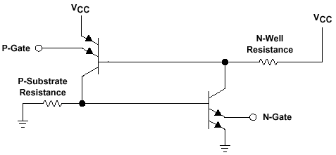

A l'intérieur de quasiment presque tous les circuits CMOS se trouvent des transistors parasites, l'un de type PNP et l'autre de type NPN.
Le couplage de ces deux transistors bipolaires est analogue à une structure de thyristor, ou tout du moins de dispositif de redressement contrôlé (SCR), comme on peut le voir sur la figure ci-contre. Chacun de ces transistors peut se mettre à conduire si l'une des jonctions PN d'entrée devient passante. Il alimente alors l'autre, le portant ainsi en saturation. On se trouve alors avec un court-circuit entre la tension d'alimentation Vcc et le potentiel de référence.
Si aucune résistance ne limite le courant de court-circuit ainsi créé, cela peut entraîner la destruction du circuit intégré.

A conventional
thyristor is fired (turned on) by applying a voltage to the base of the n-p-n
transistor, but the parasitic CMOS
thyristor is fired by applying a voltage to the emitter of either transistor.
One emitter of the p-n-p transistor is connected to an
emitter of the n-p-n transistor, which is also the output of the CMOS gate.
The other two emitters of the p-n-p and the n-p-n
transistors are connected to V CC and ground, respectively. Therefore, to
trigger the thyristor there must be a voltage greater
than V CC + 0.5 V or less than –0.5 V and there has to be sufficient
current to cause the latchup condition.
Latchup cannot be completely eliminated. The alternative is to prevent the
thyristor from triggering. TI has improved the circuit
design by adding an additional diffusion or guard ring. The guard ring provides
isolation between the device pins and any p-n
junction that is not isolated by any transistor gate. (source Texas Instrument).